
Defining Cube-Cube Relationships
This page describes how to define relationships between cubes for use in Business Intelligence.
For background information, see Summary of Model Options.
For information on how cube versions interact with relationships, consult Cube Versions and Relationships.
Also see Accessing the BI Samples.
Overview of Relationships
You can define relationships between cubes as follows:
-
One-to-many relationships. Then you can use levels of either cube in both cubes.
In one cube (the one side), the relationship behaves much like a list-based level.
-
One-way one-to-many relationships. In one cube, the relationship behaves much like a list-based level. In the other cube, the relationship is not visible.
If you define relationships, you can define a level once rather than multiple times, which minimizes the sizes of fact tables and their indexes.
The Patients sample provides five related cubes, in a folder named RelatedCubes. The following figure summarizes how these cubes are related:

The one-way arrows represent one-way relationships; the cube that has the arrow pointing away can see the levels of the other cube. The two-way arrows represent two-way relationships.
A Look at a One-Way Relationship
In this section, we examine a working one-way relationship.
The RelatedCubes/Patients cube has a one-way relationship to the RCities cube. If you open the RelatedCubes/Patients cube in the Analyzer, you see the following cube contents:
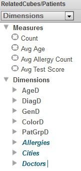
The Cities folder is a relationship to the RelatedCubes/Cities cube. If you expand it, you see the levels defined in that cube:
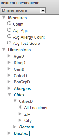
When you work with the RelatedCubes/Patients cube, you can use all these levels in the same way that you use the levels that are defined directly in this cube. For example, you could drag and drop ZIP to Rows.
The Doctors folder within Cities is a relationship from the RelatedCubes/Cities cube to the RelatedCubes/Doctors cube; it is not recommended that you use relationships of relationships, because the result quickly becomes confusing.
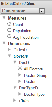
A Look at a Two-Way Relationship
There is a two-way relationship between the RelatedCubes/Cities cube and the RelatedCubes/Doctors cube. If you open the RelatedCubes/Cities cube, you see the following cube contents:
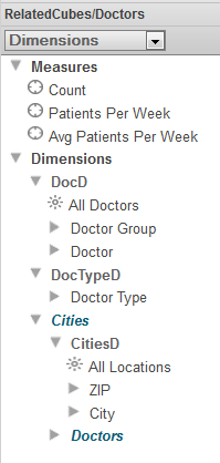
Similarly, if you open the RelatedCubes/Doctors cube, you see the following cube contents:
Defining a One-Way Relationship
To define a one-way relationship from one cube to another cube, you define a single relationship in the first cube. To do so, make the following changes in the first cube:
-
Select Add Element.
The system displays a dialog box.
-
For Enter New Item Name, type a relationship name. This determines the logical name of the relationship. It is convenient for this to be the same as the logical name of the other cube.
-
Select Relationship.
-
Select OK.
-
In the Details Area on the right, specify the following values:
Attribute Purpose Display Name Display name for this relationship. It is useful for this to be the same as the display name of the other cube. Property Specify one of these. The value must be the ID of a record in the base class used by the other cube. Expression Cardinality one Related cube Logical name of the other cube. Null replacement string (Optional) Specifies the string (for example, None) to use as the member name if the source data for a relationship is null. There is no default null replacement for relationships.
Do not specify Inverse.
-
Select the cube definition in the Architect to select it. Then edit the Depends On option in the Details Area on the right. This option specifies the class or classes that must be runnable before this class can be compiled.
By default, the system sets the DependsOn keyword equal to the name of the source class for the cube when a new cube is created.
To specify this option, specify a comma-separated list of classes and specify the full package and class name for each class in the list. Your list should include the source class for the cube and the cube class on which this cube depends. For example:
[ DependsOn = (MyApp.CubeBaseClass, MyApp.OtherCubeClass)] -
Optionally edit the cube class in an IDE to define a dependency of this relationship to some other relationship defined in the same cube.
In some cases, there is a virtual dependency between two relationships. For example, you might have a cube with a Country relationship and a Product relationship. These relationships are logically independent from each other; theoretically any product could be sold in any country. But if specific products are sold only in specific countries, there is a virtual dependency between these relationships. When a user selects a country, it is desirable to show only the products appropriate for that country.
In such a case, you can add a dependency between the relationships. To do so, specify the Depends on option as described in Defining Dependencies Between Levels in Different Hierarchies. For the value, specify the logical name of another relationship defined in the same cube. (Or, if the relationship depends upon a level, specify the MDX identifier of that level.)
Note that the Depends on attribute is completely unrelated to the DependsOn compiler keyword.
Defining a Two-Way Relationship
To define a two-way relationship between cubes, you define two complementary <relationship> elements, one in each cube. One of these cubes is the dependent cube and the other is the independent cube.
Let us consider cube A (which based on the records of source class A) and cube B (which is based on the records of source class B). To define a two-way relationship between these cubes, use the following procedure:
-
Evaluate the relationship between the source classes. Use this to determine which cube is the dependent cube, as follows:
-
Does one record in class A correspond to multiple records in class B?
If so, cube B is the dependent cube.
-
Does one record in class B correspond to multiple records in class A?
If so, cube A is the dependent cube.
-
Is there a one-to-one relationship between the classes?
If so, either cube can be the dependent cube.
-
-
In the Architect, make the following changes to the dependent cube:
-
Select Add Element.
The system displays a dialog box.
-
For Enter New Item Name, type a relationship name. This determines the logical name of the relationship. It is convenient for this to be the same as the logical name of the other cube (IndependentCubeName, for example).
-
Select Relationship.
-
Select OK.
-
In the Details Area on the right, specify the following values:
Attribute Purpose Example Display Name Display name for this relationship. It is useful for this to be the same as the display name of the other cube. Independent Cube Display Name Property Specify one of these. The value must be the ID of a record in the base class used by the other cube. Expression Cardinality one Inverse Value of the inverse relationship in the other cube. It is useful for the name of a relationship to be the same as the logical name of the cube to which it points, so use the logical name of the cube. DependentCubeName Related cube Logical name of the other cube. IndependentCubeName Null replacement string (Optional) Specifies the string to use as the member name if the source data for a relationship is null. There is no default null replacement for relationships.
None
-
-
Select the cube definition in the Architect; that is, select the top line in the middle area. Then edit the Depends On option in the Details Area on the right. This option specifies the class or classes that must be runnable before this class can be compiled.
By default, the system sets the DependsOn keyword equal to the name of the source class for the cube when a new cube is created.
To specify this option, specify a comma-separated list of classes and specify the full package and class name for each class in the list. Your list should include the source class for the cube and the cube class on which this cube depends. For example:
[ DependsOn = (MyApp.CubeBaseClass, MyApp.OtherCubeClass)] -
In the Architect, make the following changes to the independent cube:
-
Select Add Element.
The system displays a dialog box.
-
For Enter New Item Name, type a relationship name. This determines the logical name of the relationship. It is convenient for this to be the same as the logical name of the other cube (DependentCubeName, for example).
-
Select Relationship.
-
Select OK.
-
In the Details Area on the right, specify the following values:
Attribute Purpose Example Display Name Display name for this relationship. It is useful for this to be the same as the display name of the other cube. Dependent Cube Display Name Cardinality many Inverse Value of the inverse relationship in the other cube. It is useful for the name of a relationship to be the same as the logical name of the cube to which it points, so use the logical name of the cube. IndependentCubeName Related cube Logical name of the other cube. DependentCubeName -
Optionally edit the cube class in an IDE to define a dependency of this relationship to some other relationship defined in the same cube.
In some cases, there is a virtual dependency between two relationships. For example, you might have a cube with a Country relationship and a Product relationship. These relationships are logically independent from each other; theoretically any product could be sold in any country. But if specific products are sold only in specific countries, there is a virtual dependency between these relationships. When a user selects a country, it is desirable to show only the products appropriate for that country.
In such a case, you can add a dependency between the relationships. To do so, specify the Depends on option as described in Defining Dimensions, Hierarchies, and Levels. For the value, specify the logical name of another relationship defined in the same cube. (Or, if the relationship depends upon a level, specify the MDX identifier of that level.)
Note that the Depends on option is completely unrelated to the DependsOn compiler keyword.
-
Building Cubes That Have Relationships
Cubes which have relationships must be built (or rebuilt) in a particular order to avoid errors: an independent cube must be built before any related cube which depends upon it. In other words, the cube that does not define a source property or source expression for the relationship must be built before the cube that does.
However, it is rarely necessary for you to determine the order in which related cubes must be built individually. All of the interfaces which Business Intelligence provides for building a cube use the %BuildCube()Opens in a new tab method of the %DeepSee.UtilsOpens in a new tab class. To avoid errors which would occur if related cubes were built in the wrong order, this method resolves dependencies automatically: when it is invoked for a particular cube (or cubes), it collates a list which includes each specified cube as well as all of the cubes which depend upon it. Then, it builds all of the cubes in the list, determining the correct dependency order automatically.
Whether you are building related cubes through a Business Intelligence user interface (such as the Architect) or by calling %BuildCube() programmatically, simply initiate a build for the independent cube and %BuildCube() will automatically build the its dependent cubes as well.
Where possible, avoid initiating separate build operations for a cube and its dependents. Doing so results in duplicate work.
For a production system, InterSystems recommends that you use the Cube Manager. Using the Cube Manager, you can automate tasks to build and (when supported) synchronize groups of cubes according to a schedule that you specify.
Using Model Browser
The system provides a supplemental tool (the Model Browser) that you can use to view cube definitions. The Model Browser is particularly useful for cubes that have relationships because it enables you to view and navigate the cube relationships.
To access this tool, select Analytics, then Tools, and then select Model Browser.
Once you access the Model Browser, use the drop-down list on the right and select the name of a cube. The Model Browser then displays a diagram like the following:
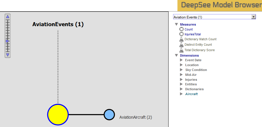
The yellow circle at the center represents the cube that you selected. The label on the top of the diagram gives the name of this cube (in this case, AviationEvents), followed by the number of related cubes (1) in parentheses. Each of the circles around the central circle represents one cube that is related to the selected cube. For these circles, the label indicates the cube name and the number of related cubes. For example, the circle labeled AviationAircraft represents the AviationAircraft cube. There are two cubes that are related to Referrals.
When you select any circle, the diagram changes so that the center shows the newly selected cube, and the rest of the diagram is refreshed accordingly.
The right side of the page displays details for the selected cube. This area displays the contents of the cube in exactly the same way as the left area of the Analyzer.
Removing Relationships
If you later decide to remove a relationship, do so as follows:
-
Remove the relationship from both cube definitions.
-
Recompile both cube definitions.
-
Rebuild all modified cubes in the correct order.